* Hoạt động cơ bản không phụ thuộc vào dụng cụ đo được điều khiển, vì vậy ngay cả khi
dụng cụ đo đã được thay đổi, DCS-100A vẫn thân thiện với người dùng.
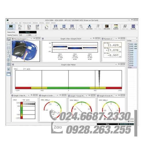
* Có thể hiển thị thời gian Y, XY, biểu đồ thanh, mét tròn và hiển thị số.
* Đo cài đặt điều kiện, thu thập dữ liệu, thu thập dữ liệu, tái tạo dữ liệu và chuyển đổi tệp. Để phân tích dữ liệu thu được, nên sử dụng phần mềm phân tích dữ liệu tùy chọn DAS-200A.
* Thu thập dữ liệu dung lượng lớn bằng đĩa cứng của PC.
* Thu thập dữ liệu tự động.
* Thao tác dễ dàng với thanh công cụ, phím chức năng và bảng thao tác
* Chuyển đổi định dạng tệp dữ liệu tiêu chuẩn Kyowa (KS2) thành định dạng CSV và Excel trong quá trình sao chép dữ liệu.
DCS-100A
Phần mềm thu thập dữ liệu động DCS-100A
Thông số kỹ thuật chung
Môi trường hoạt động
HỆ ĐIỀU HÀNH ………… Windows 8.1, Windows 10, Windows 11Tiếng Anh/Nhật, hỗ trợ 32/64 bit Nếu hệ điều hành 64-bit, hoạt động trong môi trường WOW64 (Windows 32-bit Trên Windows 64-bit).
CPU ………… Core i5 2 GHz hoặc nâng cao
Bộ nhớ ………… Nếu HĐH 32 bit, 2 GB trở lênNếu HĐH 64 bit, 4 GB trở lên
Hiển thị ………… Độ phân giải: 1024768 pixel trở lên* Giao diện LAN: 100 Base-TX trở lên
Màn hình hiển thị
Đồ thị thời gian Y ………. Cho phép lập biểu đồ tối đa 16 kênh đại lượng vật lý trên trục Y với trục X trong thời gian.1 đến 10 đồ thị trên mỗi cửa sổ
Đồ thị thời gian Y (Tất cả các kênh) ………… Cho phép tất cả các kênh có đại lượng vật lý được biểu đồ trên trục Y với trục X theo thời gian theo cùng một đường cong màu.
Đồ thị thời gian Y (DIV) ………. Cho phép lập biểu đồ lên tới 16 kênh đại lượng vật lý trên trục Y với trục X theo thời gian. Điểm 0 của mỗi kênh được di chuyển tự do đến mức mong muốn vị trí trên trục Y.
Đồ thị XY ………. Các biến của 8 kênh mong muốn, mỗi kênh cho cả trục X và trục Y được vẽ đồ thị kết hợp tự do.
Biểu đồ thanh ………… Một biểu đồ thanh có tối đa 32 kênh và 1 đến 4 biểu đồ trên mỗi cửa sổ. Có thể BẬT hoặc TẮT giữ đỉnh. (Có khả năng hiển thị các giá trị đỉnh.)
Đồng hồ đo tròn ………… Biến 1 kênh mong muốn trên mỗi đồng hồ tròn
Máy đo thanh ………… Biến 1 kênh mong muốn trên mỗi máy đo thanh ngang hoặc dọc
Windows số ………… Hiển thị dữ liệu số của 1 hoặc 16 kênh mong muốn hoặc tất cả các kênh. (Có khả năng hiển thị giá trị tối đa và tối thiểu của mỗi kênh)
Chỉ báo quá mức đầu vào ………… Có khả năng hiển thị các giá trị kênh quá mức bằng màu đỏ.
Tỷ lệ đồ thị ………… Có khả năng hiển thị các giá trị tỷ lệ tự động và tỷ lệ đầy đủ trên biểu đồ thời gian Y (trục Y), biểu đồ XY (trục X, Y) và biểu đồ thanh (trục Y) . Biểu đồ thời gian Y (trục Y) có thể thay đổi thành 1 trục, 2 trục hoặc kênh.
Màu hiển thị ………… Biểu đồ có thể thay đổi tự do theo biểu đồ
Tiêu đề và Nhãn ………… Đặt tiêu đề và nhãn mong muốn cho trục X và Y.
Số lượng cửa sổ được hiển thị đồng thời…………. Tổng cộng có 32 cửa sổ số và 32 cửa sổ đồ thị.64. (Bao gồm cả cửa sổ dữ liệu được sao chép.)*Tuy nhiên, số lượng cửa sổ có thể bị hạn chế bởi tốc độ CPU và bộ nhớ của PC.
Các đường phụ trợ ………… Có khả năng hiển thị các đường phụ mong muốn trên Đồ thị thời gian Y (trục X và trục Y), Đồ thị XY (trục X và trục Y) và Đồ thị thanh (X trục và trục Y).(Tối đa 4 đường phụ cho cả trục X và trục Y.)
Dữ liệu so sánh ………… Hiển thị dữ liệu so sánh (tệp định dạng KS2 trước đó) trên biểu đồ thời gian Y, ngoại trừ biểu đồ thời gian Y (Tất cả các kênh) và biểu đồ thời gian Y (DIV), và biểu đồ XY để so sánh dữ liệu màn hình. Kích thước của tệp dữ liệu tối đa là 10 MB. Nếu kích thước tệp vượt quá 10 MB, DCS-100A sẽ hiển thị dữ liệu 10 MB từ phần đầu của nó.
Màn hình kép ………… Có khả năng di chuyển các cửa sổ Số hoặc cửa sổ Đồ thị lên màn hình phụ.
Điều kiện kênh & Điều kiện đo
Phạm vi cài đặt ………… Máy ghi ứng dụng được cài đặt theo thông số kỹ thuật.
Thông tin TEDS ………… Tự động đọc thông tin TEDS của cảm biến và cài đặt các điều kiện kênh (chỉ cảm biến TEDS)
Lưu và tải tệp điều kiện đo ………… Có khả năng lưu và tải tệp thông tin cảm biến (tệp định dạng CSV) trên các điều kiện kênh.
Môi trường cài đặt
Đích đến của Tệp Dữ liệu ………… Dữ liệu đã đo được lưu trong phương tiện lưu trữ của máy ghi được điều khiển. Cũng có thể lưu trực tiếp vào đĩa cứng của PC, trong khi nó bị giới hạn bởi tần số lấy mẫu và số lượng kênh đo.
Tự động truyền tệp dữ liệu ………… Các tệp dữ liệu được tự động chuyển sang đĩa cứng của PC sau khi ghi xong.
Chuyển đổi tự động ………… Các tệp dữ liệu được tự động chuyển đổi sang định dạng CSV, XLS, XLSX hoặc RPC sau khi hoàn tất ghi.
Đơn vị tùy chọn ………… Đăng ký tối đa 3 đơn vị do người dùng xác định.
Chức năng TẠM DỪNG Trong khi Ghi Dữ liệu ………… Có thể BẬT hoặc TẮT chức năng TẠM DỪNG.
Hồ sơ dữ liệu
Lưu định dạng tệp ………… Định dạng tệp tiêu chuẩn Kyowa (KS2)
Khớp nối tệp ………… Các tệp dữ liệu được lưu trong bộ ghi được điều khiển hoạt động đồng bộ hóa được kết hợp thành một tệp dữ liệu duy nhất tại thời điểm PC thu thập.
Sao chép dữ liệu
Đồ thị thời gian Y ………. Cho phép lập biểu đồ lên đến 16 kênh đại lượng vật lý trên trục Y với trục X trong khoảng thời gian từ 1 đến 10 đồ thị trên mỗi cửa sổ.
Đồ thị thời gian Y (DIV) ………. Cho phép lập biểu đồ lên tới 16 kênh đại lượng vật lý trên trục Y với trục X theo thời gian. Điểm 0 của mỗi kênh được di chuyển tự do đến mức mong muốn vị trí trên trục Y.
Đồ thị XY ………. Các biến của 8 kênh mong muốn, mỗi kênh cho cả trục X và trục Y được vẽ đồ thị kết hợp tự do.
Windows số ………… Hiển thị dữ liệu số trong danh sách.
Tỷ lệ đồ thị ………… Có khả năng hiển thị các giá trị tỷ lệ tự động và tỷ lệ đầy đủ trên biểu đồ thời gian Y (trục Y), biểu đồ XY (trục X, Y) và biểu đồ thanh (trục Y) .Biểu đồ thời gian Y (trục Y) có thể thay đổi thành 1 trục, 2 trục hoặc kênh.
Màu hiển thị ………… Biểu đồ có thể thay đổi tự do theo biểu đồ
Tiêu đề và Nhãn ………… Đặt tiêu đề và nhãn mong muốn cho trục X và Y.
rigger Measurement ………… Start/stop recording based upon specified trigger conditions.
Common Trigger Conditions …………
End Trigger ………… Settable
Delay ………… Up to 262144 data for both start and end.The delay time varies with the number of channels.
Analog Trigger …………
Trigger Channels ………… Any channel
Trigger Level ………… Sets in physical quantity.
Trigger Slope ………… UpDown
External Trigger Conditions …………
Trigger Slope ………… UpDown
Composite Trigger Conditions …………
Trigger Source ………… Select from the analog channels (Any 4 channels of the master unit), external trigger, or manual trigger.Capable of judging the trigger source by using the logical AND and OR operators.
Trigger Level ………… Sets in physical quantity.
Trigger Slope ………… UpDown
Repetition Acquisition ………… In long-term data acquisition, a specified amount of data (or time) is saved in KS2 file.*Workable in manual mode (Data points preset).
Measuring Conditions for Saving Data in PC Hard Disk
Sampling Frequencies ………… 1 Hz to 100 kHz(1-2-5 series, 2n series, or external clock)
Data Files Size ………… Capacity of the hard disk
Measuring Modes ………… ManualManual (Data points preset)IntervalAnalog trigger
Manual Measurement ………… Records data from REC to STOP or from REC to the number of data, specified on the Manual (Set Record Data).
Interval Measurement ………… Records data automatically based on the preset starting time and recording interval.
Analog Trigger Measurement ………… Starts/stops recording data based on the preset trigger conditions.
End Trigger ………… Settable
Delay ………… Up to 262144 data for both start and end.The delay time varies with the number of channels.
Trigger Channels ………… Any 1 channel
Trigger Level ………… Physical quantity
Trigger Slope ………… UpDown
Static Measurement ………… Every time the DCS-100A starts recording data, the DCS-100A additionally saves the moving-averaged measured data in a single CSV format file in manual and interval modes.
Repetition Acquisition ………… In long-term data acquisition, a specified amount of data (or time) is saved in KS2 file.*Workable in manual mode (Data points preset).
NTB-500C Control specifications
Units ………… Up to 8 units (up to 64 channels.)
Interfaces ………… CAN*Uses the USB/CAN converter (LEAFLIGHT HS V2).
Data Storage ………… Saves the measured data in the PC folder in the KS2 format file.
Channel Conditions ………… Measuring ON/OFFMeasuring modeRangeZEROCalibr. const.OffsetUnitChannel nameMeasuring rangeRated capacityRated outputDeci DigitsChk. Val. (Up)Chk. Val. (Down)(Display items can freely be selected.)
Sampling Frequencies ………… 1 to 1k Hz*Limited by the communication cable length and number of channels.
Measuring Modes ………… ManualManual (Set Record Data)IntervalAnalog Trigger
Manual Measurement ………… Records data from REC to STOP or from REC to the number of data, specified on the manual (Set Record Data).
Interval Measurement ………… Records data automatically based on the preset starting time and recording interval.(5 steps, sets the recording interval of each step.)
Analog Trigger Measurement ………… Starts/stops recording data based on the preset trigger conditions.
End Trigger ………… Settable
Delay ………… Up to 262144 data for both start and end.*The delay time varies with the number of channels.
Trigger Channels ………… Any 1 channel
Trigger Level ………… Sets in physical quantity.
Trigger Slope ………… Positive or negative
TEDS ………… Loads the TEDS information automatically and sets the channel conditions.
Changing Stroke ………… Changes the data, before the stroke and after the stroke, when using a displacement transducer.
Static Measurement ………… Every time the DCS-100A starts recording data, the DCS-100A additionally saves the moving-averaged measured data in a single CSV format file.*Measure Mode: Manual and Interval only.
Repetition Acquisition ………… When recording data for a long time, the DCS-100A saves data, every preset number of data or every preset interval, in the KS2 format file.*Measure Mode: Manual (Set Record Data) only.
Environment Settings
Hardware Configuration ………… Sets the number of units, communication cable length, device names, and measuring units.Loads the hardware configurations from the NTB-500A/C.
UCAM-550A Control specifications
Units ………… Max. 6 (Max. 300 channels)Max. 20 (Max.1000 channels), optional software DCS-106A is required.
Interfaces ………… LAN
Data Storage ………… Measured data is saved to data folder in the PC in KS2 format.
Sampling Frequencies ………… 1, 2, 10, 20, and 50 Hz
Measuring Modes ………… ManualManual (Data points preset)IntervalAnalog trigger
Measuring Function ………… Measure:Measured value = Sensor output value – Initial valueOriginal:Measured value = Sensor output value
Calibration Factor Calculation ………… ON/OFF setting in all channels of one batchCalibration factor compensation:Measured value x Calibration factor + Offset
Channel Conditions ………… MeasurementModeRangeCalibration factorOffsetUnitInitial valueChannel nameMeasuring rangeDeci DigitsChk. val. (Up)Chk. val. (Down)Rated capacityRated output(Selection of any display item is possible.)
Initial Value Measurement ………… Measures the initial value of each sensor.
Manual Measurement ………… Measurement is made from a press of the REC button to a press of the STOP button or by completion of recording using a preset number of measurements.
Interval Measurement ………… Measurement is made automatically at preset intervals from the preset starting time.
Analog Trigger Measurement ………… Starts/stops recording data based on the preset trigger conditions.(Trigger level value: Fixed)
End Trigger ………… Settable
Delay ………… For both start and end, max. 3000 points/channel.
Trigger Channels ………… Any 1 channel
Trigger Level ………… Sets in physical quantity.
Trigger Slope ………… UpDown
Changing Stroke ………… Changes the data, before the stroke and after the stroke, when using a displacement transducer.
Static Measurement ………… Every time the DCS-100A starts recording data, the DCS-100A additionally saves the moving-averaged measured data in a single CSV format file in manual and interval modes.
Burnout Check ………… For USM-51B/52B only
TEDS ………… Reads sensor’s information and sets to channel condition automatically. (USM-51B/52B only)
Setting/Loading Parameters ………… Sets and loads the UCAM-550A internal parameters.
Environment Settings
Hardware Configuration ………… Sets the number of units, device names, and measuring units.Loads the measuring unit configuration from the UCAM-550A.
Communication Status ………… Loads the UCAM-550A version.
PCD-400A PCD-430A Control specifications
Units ………… Max. 4(Max. 16 channels)
Interfaces ………… USB
Data Storage ………… Measured data is saved to data folder in the PC (in KS2 format).
Channel Conditions ………… Measurement ON/OFFStrain modeRangeLPFBalance ON/OFFCalibration coefficientOffsetGage factorUnitChannel nameMeasuring rangeDeci DigitsRated capacityRated outputUpper limit checkLower limit checkOffset zero ON/OFF(Any display item is selectable)
Sampling Frequencies ………… 1 Hz to 10 kHz (1-2-5 series)
Measuring Modes ………… ManualManual (Data points preset)IntervalAnalog trigger
Manual Measurement ………… Measurement is made from a press of the REC button to a press of the STOP button or by completion of recording using a preset number of measurements.
Interval Measurement ………… Measurement is made automatically at preset intervals from the preset starting time.
Analog Trigger Measurement ………… Start/stop recording based upon specified trigger conditions.(Trigger level value: Fixed)
Trigger Conditions …………
End Trigger ………… Settable
Delay ………… For both start and end, max. 640000 data / channel.*The delay time varies with the number of channels.
Trigger Channels ………… Any 1 channel
Trigger Level ………… Sets in physical quantity.
Trigger Slope ………… UpDown
Static Measurement ………… Every time the DCS-100A starts recording data, the DCS-100A additionally saves the moving-averaged measured data in a single CSV format file in manual and interval modes.
Repetition Acquisition ………… In long-term data acquisition, a specified amount of data is saved in KS2 file at specified intervals.*Workable in manual mode (Data points preset).
Environment Settings
Hardware Configuration ………… Sets the unit names and units.Sets the unit name to the PCD-400A series.Loads the number of units from the PCD-400A series.
Automatic Data File Conversion ………… Automatic file conversion upon the termination of measurement(CSV, XLS, XLSX, and RPC formats)
Arbitrary Unit Settings ………… 3 user-defined units can be registered.
EDX-5000A Control specifications
Units ………… Max. 10 (Max. 800 analog channels, Max. 10 digital channels)*EDX-5000A + EDX-3000B, EDX-5000A + EDX-200A available.Max. 8 units: EDX-5000A + EDX-200A
Interfaces ………… LAN (100BAST-TX, 1000BASE-T)
Data Storage ………… Measured data is saved in the EDX-5000A data drive and/or data folder in the PC in KS2 format.
Channel Conditions ………… Measurement ON/OFFModeRangeHPFLPFBalance ON/OFFCAL rangeCAL ON/OFFCalibration coefficientOffsetUnitChannel nameMeasuring rangeRated capacityRated outputDeci DigitsChk. val. (Up)Chk. val. (Down)Internal sensitivity compensation ON/OFFOffset ZERO ON/OFFDigital filter(HPF: Any cutoff frequency, LPF: Any cutoff frequency)(Selection of any display item is possible.)
TEDS ………… Reads sensor’s information and sets to channel condition automatically.
Setting/Loading Parameters ………… Sets and loads the EDX-5000A internal parameters.
Collecting Data ………… Collects data saved in the data drive in the EDX-5000A. (KS2, E4A, NMEA)
Erasing Data ………… Erases data saved in the data drive in the EDX-5000A. (KS2, E4A, NMEA)
Environmental Settings …………
Hardware Configuration ………… Sets the number of units and device names.Loads the hardware configurations from the EDX-5000A.
Communication Check ………… Loads the EDX-5000A version.
Device Confirmation ………… LEDs, on the EDX-5000A front panel, light up.
Others ………… Oscillator switching (internal/external)Operating beep soundBalance standard valueAD data format (16 bits/24 bits)
DIO Settings ………… Number of input/output points: Up to 8Digital input/Digital output/Remote control (input) for every bit.
Measuring Conditions for Saving Data in EDX-5000A Data Drive
Sampling Frequencies ………… 1 Hz to 200k Hz (1-2-5 series, 2n series, or external clock)*Depends on the measuring channels and measuring units.
Data File Size ………… Capacity of the hard disk
Measuring Modes ………… ManualManual (Data points preset)IntervalAnalog triggerExternal triggerComplex trigger
Manual Measurement ………… Measurement is made from a press of the REC button to a press of the STOP button or by completion of recording using a preset number of measurements.
Interval Measurement ………… Measurement is made automatically at preset intervals from the preset starting time.
Trigger Measurement ………… Start/stop recording based upon specified trigger conditions.
Common Trigger Measurement …………
End Trigger ………… Settable
Delay ………… For both start and end, max. 4194304 data.*The delay time varies with the number of channels.
Analog Trigger Conditions …………
Trigger Channel ………… Any 1 channel of the master unit
Trigger Level ………… Sets in physical quantity.
Trigger Slope ………… UpDown
Digital Trigger Conditions …………
Trigger Bit ………… Any 1 channel of the master unit
Trigger Level ………… 0, 1
External Trigger Conditions …………
Trigger Slope ………… UpDown
Composite Trigger Conditions …………
Trigger Source ………… Selects from analog channels (any 4 channels of the master unit), external trigger, ECAN trigger, or manual trigger.Capable of judging the trigger source by using the logical AND and OR operators.
Trigger Level ………… Sets in physical quantity.
Trigger Slope ………… UpDown
Repetition Acquisition ………… In long-term data acquisition, a specified amount of data (or time) is saved in KS2 file.*Workable in manual mode (Data points preset).
EGPC-50A …………
CAN Data Acquisition ………… Max. 512 channels/unit of CAN data is possible.(CAN data is saved to EDX-5000A data drive, as the E4A file.)
Point ZERO Manual Measurement ………… Starts the manual measurements of multiple EDX-5000A units at 0 ms by using the time data, received from the GPS satellite.
GPS Synchronous Interval Measurement ………… Starts the interval measurement of multiple EDX-5000A units at 0 ms by using the time data, received from the GPS satellite.
GPS Data Acquisition ………… Monitors and records GPS data such as latitude, longitude, direction of movement, speed.GPS data is saved in EDX-5000A data drive as NMEA format.
Measuring Conditions for Saving Data in PC Hard Disk
Sampling Frequencies ………… 1 Hz to 10k Hz (1-2-5 series, 2n series, or external clock)*Depends on the measuring channels and measuring units.
Data File Size ………… Capacity of the hard disk
Measuring Modes ………… ManualManual (Data points preset)IntervalAnalog trigger
Manual Measurement ………… Measurement is made from a press of the REC button to a press of the STOP button or by completion of recording using a preset number of measurements.
Interval Measurement ………… Measurement is made automatically at preset intervals from the preset starting time.
Analog Trigger Measurement ………… Start/stop recording based upon specified trigger conditions.
End Trigger ………… Settable
Delay ………… For both start and end, max. 4194304 data.*The delay time varies with the number of channels.
Trigger Channels ………… Any 1 channel of the master unit
Trigger Level ………… Sets in physical quantity.
Trigger Slope ………… UpDown
Repetition Acquisition ………… In long-term data acquisition, a specified amount of data (or time) is saved in KS2 file.*Workable in manual mode (Data points preset).
CTRS-100A Control specifications
Number of Units ………… Up to 4 units(Up to 128 analog channels.)
Interface ………… USB (USB2.0 High Speed) or Ethernet* (10/100BASE-T) *A separate synchronous unit and special communication cable are necessary.
Saving Format ………… Saves the measured data in the CTRS-100A SD card or PC folder.When saving to the SD card of CTRS-100A, save the KS3 file.When saving to PC folder, save as KS3 file or KS2 file (01.06).
Channel Conditions ………… Measuring ON/OFFMeasuring modeRange (Arbitrary input)HPFLPFBalance adjustment ON/OFF/NONEInput resistance check ON/OFFCalibr. const.OffsetCable correction valueOffset ZERO ValueUnitChannel nameMeasuring rangeRated capacityRated outputDeci DigitsChk. Val. (Up)Chk. Val. (Down)Offset ZERO ON/OFFTEDS User DataTEDS Sensor ModelTEDS Sensor S/NTEDS ROMID(Display items can freely be selected.)
TEDS ………… Loads the TEDS information automatically and sets the channel conditions.
Setting Parameter and Loading Parameter ………… Loads and sets the CTRS-100A internal parameter.
Saving and Loading Meas Condition File ………… Loads and saves the meas condition file.(Extension: C1H)The meas condition file includes environment settings, channel conditions, measuring conditions, display conditions on graphs and on numeric windows, and arithmetic operation conditions (Optional).
Saving and Loading CTRS-100A Condition File ………… Loads and saves the CTRS-100A condition file (Extension: SET) by using the SD card.
Collecting Data File ………… Convert KS3 files and KC3 files in CTRS-100A SD card. (KS3 files can be converted to KS2 files and collected.)
Deleting Data File ………… PC deletes the KS3 files and KC3 files, saved in the CTRS-100A SD card.
Formatting SD Card ………… PC formats the CTRS-100A SD card.
Setting Environment …………
Setting Hardware Configuration ………… Sets Interface, the number of units and device names.Loads the hardware configurations from the CTRS-100A.
Communication Check ………… Loads the CTRS-100A version.
Device Confirmation ………… LEDs, on the CTRS-100A front panel, light up.
Others ………… Remote control unit operation beep, balance standard value, PAUSE ON/OFF, detailed hardware information display
When CAN Unit is Installed …………
Recording CAN Data ………… Records up to 1024 message CAN data per one unit (as the KC3 file).*When saving to PC folder, up to 1 CAN unit to be measured.
CAN Data Output ………… StartStopIntervalManual
When Saving the Measured Data in the CTRS-100A SD Card
Sampling Frequencies ………… 1 Hz to 100k Hz(1-2-5 series, 2n series, external clock)*Limited by the number of channels.
Number of Data/CH ………… Up to 1000000000 data
Measure Modes ………… ManualManual (Set Record Data)IntervalAnalog TriggerExternal TriggerManual TriggerComplex TriggerCAN Trigger**CAN units are required.
Manual Measurement ………… Records data from REC to STOP or from REC to the number of data, specified on the Manual (Set Record Data).Recording start time settable.
Interval Measurement ………… Records data automatically based on the pre-set starting time and recording interval.
Trigger Measurement ………… Starts/stops recording data based on the preset trigger conditions.
Common Trigger Conditions …………
End Trigger ………… Settable
Delay ………… Up to 524288 data for both start and end.*The delay time varies with the number of channels.
Analog Trigger Conditions …………
Trigger Channels ………… Any 1 channel of the master unit
Trigger Level ………… Physical quantity
Trigger Slope ………… Positive or Negative
External Trigger Conditions …………
Trigger Slope ………… Positive or Negative
Manual Trigger Conditions …………
Complex Trigger Conditions …………
Trigger Source ………… Select from the analog channels (any 4 channels of the master unit), external trigger, or manual trigger.Capable of judging the trigger source by using the logical AND and OR operators.
Trigger Level ………… Physical quantity
Trigger Slope ………… Positive or Negative
CAN Trigger Conditions …………
Common CAN Trigger Conditions …………
End Trigger ………… Settable
Delay ………… Only end.With measurement channel: Up to 174762 s.No measurement channel: Up to 65535 s.*The delay time varies with the sampling frequency and the number of channels.
Manual Trigger Conditions …………
Analog Trigger Conditions …………
Trigger Channel ………… Any 1 signal of the master unit
Trigger Level ………… Physical quantity
Trigger Slope ………… Positive or Negative
Digital Trigger Conditions …………
Trigger Channel ………… Any 1 signal of the master unit
Trigger Bit ………… Any 1 bit
Trigger Slope ………… Positive, Negative, Level
Complex Trigger Conditions …………
Trigger Source ………… Trigger channel (Any 8 signals of the master unit)Select from analog trigger or digital trigger.Trigger sources can be logically identified by AND/OR at once.
Repeated Recording ………… When recording data for a long time, the DCS-100A saves data, every preset number of data or every preset interval, in the KS3 format file. *Measure Mode: Manual (Set Record Data) only.
Data File ………… File name, File TitleGrant rule: File No. or Recording start time.File No.: 3 to 5 digits.
When Saving the Measured Data in the PC Folder
Sampling Frequencies ………… 1 Hz to 100k Hz(1-2-5 series, 2n series, external clock) *Limited by the number of channels.*CAN data recording in synchronous operation: 5 kHz or less
File Size ………… Up to the data drive capacity.
Measure Modes ………… ManualManual (Set Record Data)IntervalAnalog Trigger
Manual Measurement ………… Records data from REC to STOP or from REC to the number of data, specified on the Manual (Set Record Data).
Interval Measurement ………… Records data automatically based on the preset starting time and recording interval.
Analog Trigger Measurement ………… Starts/stops recording data based on the preset trigger conditions.
End Trigger ………… Settable
Delay ………… Up to 524288 data for both start and end.*The delay time varies with the number of channels.
Trigger Channels ………… Any 1 channel
Trigger Level ………… Physical quantity
Trigger Slope ………… Positive or Negative
Static Measurement ………… Every time the DCS-100A starts recording data, the DCS-100A additionally saves the moving-averaged measured data in a single CSV format file.*Measure Mode: Manual and Interval only.
Repeated Recording ………… When recording data for a long time, the DCS-100A saves data, every preset number of data or every preset interval, in the KS2 format file.*Measure Mode: Manual (Set Record Data) only.
Data File ………… File name, File TitleGrant rule: File No. only.File No.: 4 digits only.
Nhà phân phối, Đại lý bán sản phẩm Phần mềm thu thập dữ liệu động Phần mềm thu thập dữ liệu động KYOWA DCS-100A ở đâu?
tek-ac.com cung cấp sản phẩm chính hãng Phần mềm thu thập dữ liệu động Phần mềm thu thập dữ liệu động KYOWA DCS-100A tại Việt Nam, các sản phẩm được nhập khẩu đầy đủ phụ kiện chứng từ. Hãy liên hệ với chúng tôi ngay hôm nay để được hỗ trợ về sản phẩm.
Nơi bán sản phẩm Phần mềm thu thập dữ liệu động Phần mềm thu thập dữ liệu động KYOWA DCS-100A giá tốt nhất
tek-ac.com cung cấp Phần mềm thu thập dữ liệu động Phần mềm thu thập dữ liệu động KYOWA DCS-100A với giá cả và thời gian giao hàng cạnh tranh. Giao hàng toàn quốc, có cung cấp dịch vụ lắp đặt và hướng dẫn sử dụng nếu quý khách yêu cầu.
Mua sản phẩm Phần mềm thu thập dữ liệu động Phần mềm thu thập dữ liệu động KYOWA DCS-100A ở đâu?
Bạn đang cần mua Phần mềm thu thập dữ liệu động Phần mềm thu thập dữ liệu động KYOWA DCS-100A? Hãy liên hệ với chúng tôi ngay hôm nay, tek-ac.com có nhiều năm kinh nghiệm cung cấp sản phẩm, quý khách nhận được tư vấn kỹ thuật, ứng dụng sản phẩm và các dịch vụ hậu mãi sau bán hàng.
Bạn cần thêm thông tin về sản phẩm này, ứng dụng, hàng mẫu? Hãy liên lạc với chúng tôi theo số Tel (024) 6687-2330 / sale@tek-ac.com Bạn cũng có thể gửi câu hỏi bằng cách điền thông tin theo mẫu Contact Us, hoặc nhắn tin qua hộp hội thoại Chat ở góc phải màn hình.
